
HUBS, WHEELS, AND TIRES
Indy cars had wire wheels with knock-off hubs. Of course, there were several manufacturers of wire wheels in those days and wheels were not interchangeable. Studebaker learned the hard way in the 1932 race when tires started wearing out early and they borrowed wheels from an adjoining pit crew. The wheels came loose with much grief. To avoid that problem, I tried to stick with commercially-available wheels and hubs while retaining the correct appearance. Alas, I had to make custom hubs and wheels.
A major issue was the size of inner and outer wheel bearings on the front axle. The inner races are 3.00" diameter, so the hubs had to hold these bearings and provide enough strength to support the car under normal and impact loads. It's not easy to guess the impact loads, so conservative engineering design was used, i.e., use more steel. I first contact Dayton Wire Wheel, an old U.S. firm, for hubs and wheels. Wheel choices were straight forward and reasonably priced, but they could not offer a hub that would accommodate the bearing race and wouldn't discuss a custom hub.
I researched the available information about Rudge-Whitworth hubs and wheels and found that there was a range of sizes designed in 1909-1912 to accept bearings of different sizes. The Rudge hubs were named for the maximum size of bearing race (in millimeters) they would accept. Unfortunately, there was nothing available through Googling or through the AACA library that defined the dimensions of the splined hubs, except in the most general terms. While a number of firms offered replacement hubs for old MGs, Jaguars, Bentleys, etc., none of them would discuss custom hubs to fit a 1929 Studebaker President spindle with 1963 Buick Riviera brake drums or share drawings of what they had available. I made a number of phone calls to suppliers in the U.S., New Zealand, and the UK to pursue anyone who could supply parts. In the end, I found some details for the splines and inside diameters of some Rudge hubs from a 1974 article by Alex Ulmann in "The Bulb Horn" magazine of the Veteran Motor Car Club of America (VMCCA). Using these numbers, copies of original drawings of the spindles from the Studebaker National Museum, and careful measurements of Buick drums, I was able to make detailed 3D CAD drawings of front and rear hubs using TurboCAD Pro software.

As a calibration, old MG-TDs used 42 mm hubs, Jaguar XK-120 through XKE used 52 mm, and the big Bentleys of the 1920s-30s used 62 mm hubs. I may have been overly conservative in how much steel I wanted to support the bearings, but I settled on the 72 mm size. It turns out that this is a rare size, but the 80 mm and up sizes are even more rare. I haven't had the opportunity to get actual dimensions from the original Indy cars, but I will check this someday.
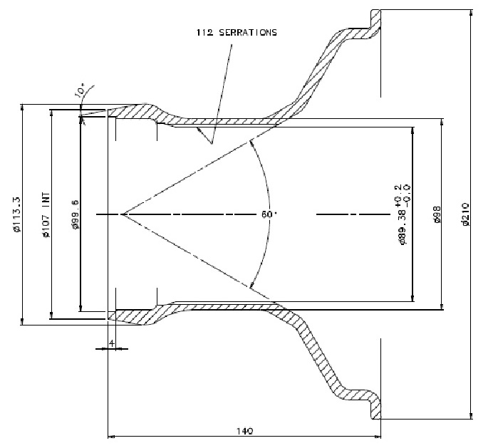
The 72 mm hubs required 112 splines of 60 degree angle at 10 pitch. That is, base circle of 1" circumference would accommodate 10 teeth, so 112 spines required a circumference of 11.2 inches or a mean diameter of 11.2"/pi = 3.565 inches. The inner and outer tip radii were defined as 0.016 inch, which set the maximum outside diameter of the hubs and the way the splines had to be cut. Additionally, there were threads (3.062 o.d. x 8 threads/inch) outside the splines for the knock-off spinners to engage, left-hand threaded on the right side of the car and right-hand threaded on the left side. Grease seal caps thread into the inside of the hubs to retain wheel bearing grease. It became clear to me that, while the Rudge hubs were nominally dimensioned in millimeter sizes, the basis was on the good, old Imperial system using inches, so most of the metric dimensions rounded off to 1/8", 1/16", 1/32", or 1/64".
I was fortunate to obtain a detailed drawing of a 72 mm-size wheel center that goes over a 72 mm splined hub. That defined the tapered cone mating surface of the wheel where it contacted the hub. The key theory of the Rudge hub is that the wheel is centered between the inner 60-degree cone of the hub and a 10-degree tapered surface at the outer end of the wheel center. The inside surface of the spinner is also tapered at 10 degrees to mate with the wheel center. Because of the left/right threading for the spinners, each time the car moves forward, it tightens the spinner (if needed), keeps the wheel centered on the spindle axis, and pushes the wheel against the inner cone on the hub. The wheel center can't contact the brake drum surface or it won't stay tight. Additionally, the spinner has to have enough threads engaged to provide tight clamping force and must seat against the outer wheel cone without touching spokes or anything else. This doesn't leave much tolerance for error.
So, after obtaining copies of the original drawings of the 1929 President front axle, knuckle/spindle, front and rear hubs, I set about the detailed design of how to match the spindles to the 1963 Buick Riviera brake backing plates and drums and the splined section of the new hubs. The bearing locations and sizes dictated many of the dimensions, as well as the inner grease seals. The rear hubs had to fit on the tapered axle shafts. In order to be able to pull the hubs off the rear axle, the hubs were made in two pieces: an inner hub with a tapered bore and an outer splined hub that fit over the inner hub and sandwiched the brake drum between them. The rear inner hub incorporates five 1/2-20 studs to hold the assembly together. The studs and lug nuts are hidden by the wheel center. The front hub includes a small cross-drilled hole to allow the cotter pin to be inserted through the end of the spindle once the nut has been tightened for the correct bearing play. Here are some hub drawings to illustrate the complex details.

Getting the hubs made was a challenge - no local shop wanted to take on the job. Fortunately, I have a friend who runs a small design and manufacturing company that operates from China. He goes to China several times a year to do projects for his U.S. and international customers. He has good connections with many shops in the Guangzhou area, about 50 miles from Hong Kong. As he left Boston for one of his trips to China, I handed him a spare wheel center to use as a gauge to check spline dimensions and fit, as well as a bunch of 3D CAD files of all the parts. Since he has a range of old cars of his own, he understood what had to be done. The hubs were machined from 7 inch diameter billets of 4140 steel. The hunks started at 40 lbs, were machined down to about 8 lbs. While I had considered heat treating the machined parts to boost their strength and toughness, in the end we decided to skip the heat treatment because of the risk of warping the splines. The 4140 steel is already very strong. The pockets for the bearing cups had to be machined and ground to a tolerance of 0.001 inch. The splines were cut on a horizontal mill using a custom-made cutter, one spline at a time.
The shops in China did a great job. The hubs came out just right, as well as the spinners and the grease seal caps, laser engraved brass with the Studebaker logo. My buddy even made a special wrench to put the caps on.

The Studebaker Indy cars used 18-inch tires, 6.50-18 in the front and 7.00-18 in the rear. Original rims had lock rings to allow mounting the tires easily and then locking the bead in place. Not many tire shops will handle those rims these days because of safety reasons - if the rim isn't locked tight, it can blow off with deadly results to the person working on the wheel. I chose drop-center rims, 4.5 inches wide, without the lock rings to make my life a little easier in the future. The next major decision was how much offset was required. Depending on how the wheel is laced, the rim can be moved inward or outward with respect to the wheel center. Ideally, the king pin axis will intersect the ground in the middle of the tire patch; that is, where the tire is in contact with the ground. The king pins are tilted forward at the bottom and 8 degrees outward to achieve this. To help make steering easy, the spindle tips are tilted 1 degree downward, in addition. So, the dimensions of the king pins and spindles, along with the 31 inch height of the tires determined where this spot is. In the end, we were able to reduce the "scrub radius" to less than 3/4 inch.

I was fortunate to establish good communications with Motor Wheel Service (MWS) in Slough, England, right next to Heathrow Airport. See www.mwsint.com. Gary Gardner was able to guide me through the process of selecting wheel centers, rims, and spoke pattern to meet my needs. He explained that nearly 35 years ago, Dunlop had sold the design data, drawings, and tooling for making Rudge-Whitworth style wire wheels to Wheels India. Today, wheel centers, rims, and even complete wire wheels are manufactured in India and shipped to dealers around the world. The market for real knock-off wheels and hubs is mostly for older British sports cars - and a few eccentrics like me. In the U.S., Dayton Wire Wheel is the major supplier, but they have a completely different style of hub and wheel center.
Once the wheels were ordered, it took a couple of months for them to get built. As it happened, my wife and I were in England in the spring of 2014 and were able to visit MWS just as the wheels were completed. We got the full tour of the shop from Gary and the other people there. It's a clean, modern facility with lots of wheels and good equipment to build, powder coat, balance wheels, and mount tires. MWS also shipped the special racing tubes with brass stems required for participation in vintage racing events, plus the rim bands to prevent the spokes from poking holes in the inner tubes.
 |
 |
 |
Eventually, I received the four wheels at home. Remarkably, U.S. Customs didn't demand a lot of money to import the wheels. I ordered the new Excelsior radial-design tires from Coker and had them mounted at one of the last real wheel shops in New England, Wheel Repair Service in Auburn, Mass. Fred Belanger prepped the new wheels, put on the wheel bands, and installed the tubes and tires. Then he balanced the wheels, putting the adhesive weights inside the rims so they wouldn't show on the outside. Fred is a real craftsman, one of the last guys who know how to mount tires and balance wire wheels. See http://www.wheelrepairservice.com/. Eventually, I got them home, put the hubs on the axles, and finally mounted the wheels and tires.
 |
 |
At long last, here is the chassis with the springs, axles, wheels, and tires mounted, and the chassis is sitting on the ground on its own wheels. It felt good!
